Posted on 3/6/2013
Source: Aerospace Engineering
Engineers tasked with designing more efficient airframe wing boxes are confronted with a host of challenges. All aspects of the entire structure must be optimized, while also managing extensive engineering data and resolving a number of manufacturability issues—especially where composites and hybrid laminates are concerned. Even with today’s sophisticated CAD and FEA software, barriers to innovation still exist throughout the industry.
This is due to significant limitations built into many of today’s standard industry processes. For one, unnecessary weight is consistently added on, since engineers have only a partial view of options and are forced to overdesign to be “safe” within the fast-paced design-cycle schedule. Optimization tools are also not as integrated with a customer’s process as they should be, leaving that significant task for engineers to do manually. And the very nature of design is iterative. This necessitates the swapping of critical data back and forth, often from multiple engineering groups. Given the growing adoption of complex composites in wing box and other airframe structures—as in the Boeing 787, Airbus 350, and Bombardier Learjet 85 and CSeries—analysis is now a highly complicated exercise involving layups in some areas that are nearly 100 plies thick.
Some specialized CAD-based composite software packages offer partial solutions to these problems. These tools can be used with FEA on the analysis side to provide a degree of efficiency and process integrity. They are able to simulate and graphically represent details—such as ply drape and rosette angle changes across a part’s curved surface—and can pass cutting-pattern data directly to fabrication equipment on the factory floor. But while they are useful on the manufacturing side, none of these tools are able to explore composite structures in an integrated design and analysis way to provide the extensive trade-off studies and weight-reduction calculations necessary to win today’s competitive battles for the best ideas.
Addressing many of the current limitations in airframe design, HyperSizer from Collier Research Corp. offers design, analysis, and optimization solutions for both composites and metals. Used on NASA’s current Space Launch System (SLS) heavy launch vehicle, and in higher volume by a variety of leading Tier 1 and 2 aircraft manufacturers, the software can be deployed from one end of the design process to the other. In this role, it serves as an independent and neutral hub for industry-accepted CAD, FEA, and composite software, automating data exchanges without loss of information or extra engineering effort. More specifically, with HyperFEA it automatically iterates in a continuous loop with FEA solvers, searching for lightweight structurally sound options and visualizing structural details to the ply level. It also complements the various composite codes, while doing things like defining laminate zones, determining sequencing and interleaving, and minimizing ply drops/adds.
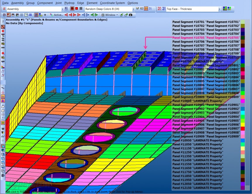
The standard industry practice today is to use two types of finite element models (FEMs) in the design of metallic and composite wing boxes and their associated stringer/stiffener, spar, rib, and skin components. The process generally begins with a smeared model in the preliminary design phase, during which all sizing variables are optimized concurrently. Having decided on stiffener location—and “frozen” tooling specifications—analysts then may transition their 2-D smeared models to 3-D discrete stiffener models (DSM). In this stage, engineering teams typically perform detailed structural analyses for all key panel-segment components. As the design progresses, other cross-sectional dimensions are locked down, too. Laminate specifications are finalized, and margins of safety calculated, with failure analyses documented for all parts required for flight certification. But these accepted practices can be enhanced further.
Using HyperSizer software during preliminary design, the engineering team can explore a more wide-open conceptual space and perform trade studies involving thousands of alternatives. This enables the calculation of robust and minimal weights for each option, an approach that leads to the greatest overall weight savings and to multiple alternatives for considerations such as cost. HyperSizer also determines initial sizing based on fiber orientation and thickness and can handle tasks such as modeling a stiffened panel or accurately representing any panel shape/size, while extracting individual panel loads for each. With the smeared model, the structure’s stiffeners are represented using a single plane of shell elements, which helps in the optimization of stiffener spacing. By optimizing placement early in design, the team can effectively eliminate the need to come back later and remake the model.
During structural analysis, HyperSizer provides additional automation of workflows. All material, loading, and sizing data can be automatically transferred intact from the smeared to the discrete stiffener model. Once in the DSM, the stringers are represented individually by beam or shell elements, or a combination of the two. Engineers can then identify each stiffener as a separate panel segment, select failure analyses, and determine unique margins of safety for each. With this added flexibility, they can create panel bays with stringers of varying dimensions and materials and capture the strength and weight benefits of non-uniform spacing and termination. Other advantages include interpreting how the stringers and skins fit together to form a stiffened panel, calculating stiffener spacing and heights automatically, and mapping the loads for crippling and buckling analyses.
In addition, a six-step process included in HyperSizer generates effective laminates, defines laminate FEM zones, and performs ply-count compatibility. It also helps the design team produce discrete laminates, create the most effective sequencing, and finalize layup specifications. These steps lead to a reduction in ply drops and fabrication steps, such as fewer layer applications on the tool and fewer ply cuts. As a result, airframe customers have reduced the weight of their structures by as much as 20%.