Open topic with navigation
Features > Components > Smeared Panels > Creating - Automatic Refining
Creating Smeared Panel Components - Automatic Refining
Important: The purpose of this process is to minimize weight by grouping together elements that, based on loading, should have similar cross-sectional dimensions and stacking sequences.
This process automatically creates smeared components within an assembly. The number and shape of the components is based on the characteristics of the element forces and a user-defined level of granularity. This step is primarily intended for defining optimum composite laminate transitions for minimizing ply drops but can also be used for metals.
Once redefined, the new sizing components can be exported into the FEM using the update FEM. See Update FEM.
How to automatically refine smeared panel components
- Open the FEM Viewer.
-
Select the assembly of interest as the active assembly. See Setting the Active Assembly.
It is important that all the components in the assembly have been fully defined with dimensions and materials.
-
In the Assembly menu select Assembly | Auto Redefine Components.
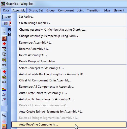
The Define Laminate FEM Zones dialog appears.
-
Select Analyze. During this analysis, HyperSizer is sizing each element in the assembly and storing the optimum thickness & width dimensions, as well as optimum ply counts for each variable of the panel. For each element the component sizing bounds are used to size the element to all active load cases.
Once complete, the Analyze button is disabled and the following steps become active.
Tip: This step only needs to be done once for any assembly. Only perform this step again (click Update) if you change the sizing variables, failure analyses or active load cases for any component in the assembly.

- In the "Initial Component Generation" frame, use the slider bar to select the desired granularity, more components vs. less components.
-
Click Generate.
This operation performs the initial grouping of elements based on the optimum dimensions, thicknesses and ply counts for each variable. If either of the skins or stiffener laminates differ, than a new component is identified from the combination of unique sizing variable laminates.
When complete, the number of components and their combined weight is reported in the form. The proposed new layout will be displayed in the FEM viewer by selecting Show in Graphics.
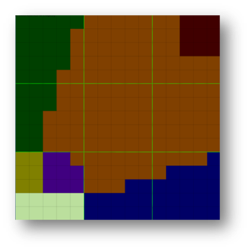
Example: Shown below is an original nine-component (laminate zone) FEM. The images to the right are results from moving the slider bar to different positions. Each color represents a unique laminate specification, or to be more technically correct, unique sizing component.


- In the "Final Component Generation" frame, use the slider bar to select the desired granularity, more components vs. less components.
-
Click Generate.
This operation performs a post processing to regroup the elements to reduce the number of very small, irregularly shaped zones. The new proposed component definition will appear.
Tip: Since these operations run very fast, it is intended for the user run the initial and final component generation steps several times with different slider bar settings to interactively evaluate different component definitions.
Example: Shown below are the proposed component definition, before and after running the "Final Component Generation" process.

- If satisfied with the new proposed layout, click Commit Changes.
-
(Optional) Clean up the new component definitions manually. See Creating Smeared Panel Components - Manual.
The images below show the zones being manually changed resulting in a five-component assembly.