
The Detail window displays the cross section, buckling deformation, and hole deformation for the active component.
To browse through options in the Detail window, click the arrow beside the Window button and the Window drop-down menu will appear.
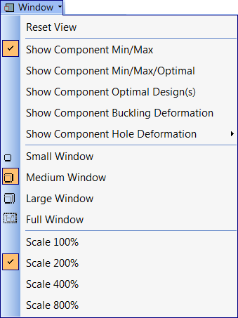
The Window drop-down menu is separated into three main sections that group the detail plotting options by their common function.
The first group of options are the plotting capabilities available in the detail window:
The second group of options allow the user to dictate the size of the Detail window, small, medium, large or full window.
The last group of options allow the user to exaggerate the thicknesses and buckling deformations displayed in the Detail window.
Important: If the scale is modified, the component must be reanalyzed in order to see the changes in the window.
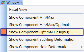
How to Show Optimal Designs in Detail Window
Make the component active by selecting it from the Active menu.
Important: To view the Component Optimal Design(s) plot in the Detail window, the component must have valid sizing results.
Choose the "Show Component Optimal Design(s)" option in the drop-down menu
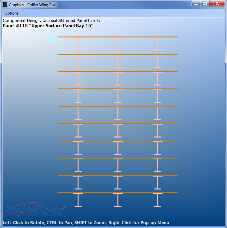
There may be multiple designs in the detail window, as shown below. These cross sections correspond to the multiple solutions that are stored for the active component.
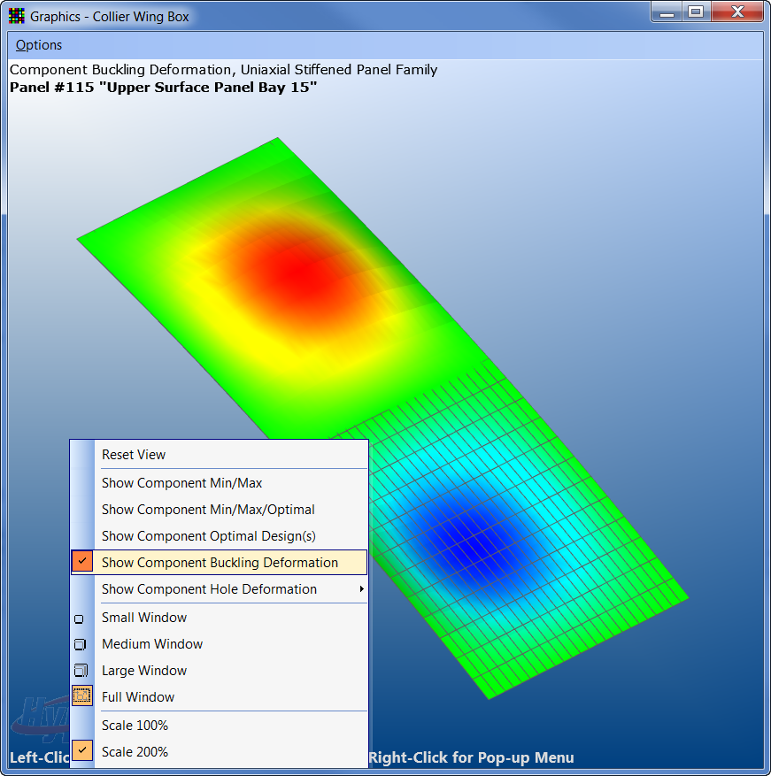
How to Show Buckling Mode Shapes in Detail Window
Important: The buckling mode shape is only available when the "Panel Buckling, Energy Solution, All BC" failure mode is selected.
Select Show Component Buckling Deformation. The number of half-modes is displayed graphically. The exact buckling mode shape that you see depends on the buckling results for the active component. The buckling mode shape is sensitive to the loads, panel bending stiffness and the analysis input on the buckling tab, such as the buckling span, radius of curvature and buckling boundary conditions.
![]()