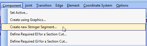
In the menu select Component | Create new Stringer Segment.
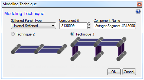
The modeling technique dialog appears.
Select the "Stiffened Panel Type", "Component #", and "Component Name".
Select the modeling technique: 2 or 3.
If viewing by assembly, you will be prompted to add this stringer segment to the current assembly.
Click Yes.
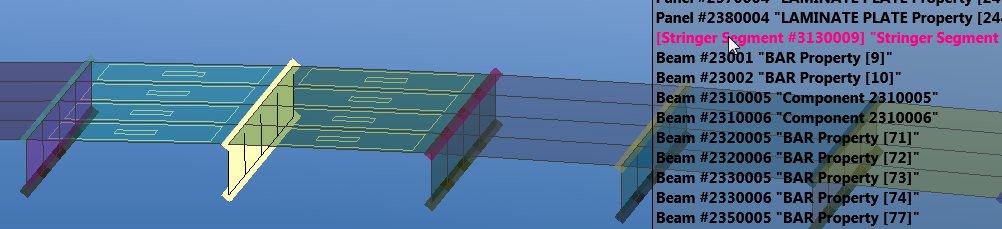
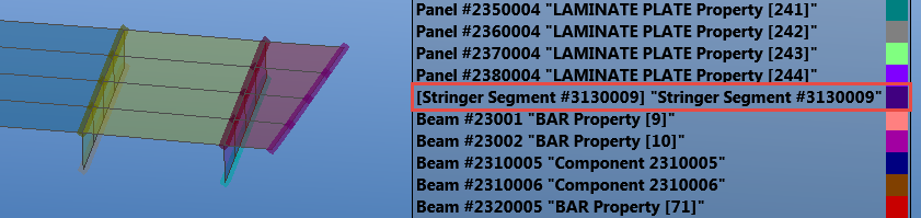
In the legend you should see a new stringer segment component. This component should also be active (denoted by square brackets in the legend). See Show Legend.
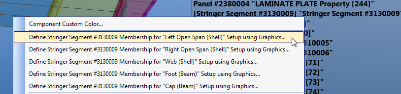
Select the left skin elements (open span). Right-click the component in the legend and select Define Stringer Segment Membership for "Left Open Span".
The pick form appears.
Verify that the Half-Bay/Full-Bay setting is set to Full-Bay.
Full-bay indicates that there is an entire skin span between this stiffener and the adjacent stiffeners. At the leading and trailing edges, you may need to select half-bay if the skin object is only a partial bay.
This setting only applicable to skin objects.

Select the elements for the right skin.
(Optional) Verify your selections by hovering the mouse over the component in the legend. All elements associated with the stringer segment will be highlighted.