There are two methods for extracting section properties from the FEM Viewer.
Important: For accurate section properties, sizing results should exist for each component that intersects the cut plane.
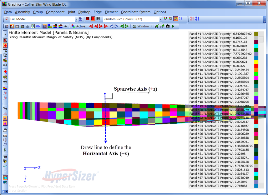
How to manually create a single section cut plane using the FEM Viewer
Hold the [Ctrl+Shift+Alt] keys and draw a line defining the horizontal axis of the cut plane. The spanwise direction is assumed at 90 degrees to the horizontal axis.
Tip: A cut plane is created and the cross section is generated based on the display. In this example the active view is "Full Model" so any element in the model that intersects the cut plane are considered when generating the section cut. Components can be removed from the cross section by selecting an assembly and modifying the active view to "Assembly".
The vertical axis is determined as the cross product of the horizontal axis and the spanwise axis.
Vertical Axis = (Horizontal Axis) x (Spanwise Axis)
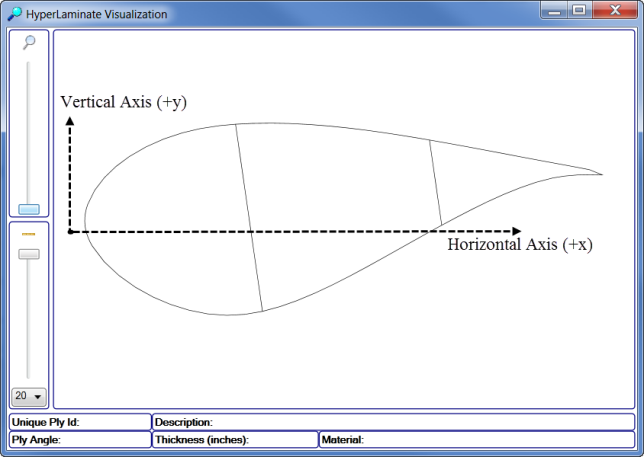
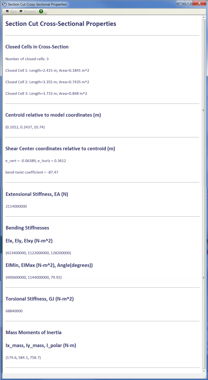
The cross sectional properties are displayed relative to the Horizontal (x) and Vertical axis (y).
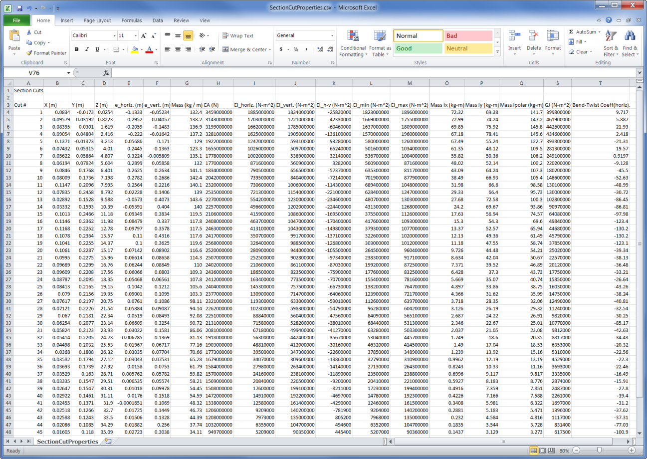
How to export a section cut spreadsheet using the FEM Viewer
Important: The section cut spreadsheet reports the section properties based on the Active Assembly. If a component is displayed that is not in the active assembly, it will not be used to compute the section properties.
Tip: To export the section properties for the entire structure make an assembly and include all components in the model.
Important: The spanwise direction (Z) is always assumed as the +z direction, relative the global coordinate system.
![]()