Posted on 3/1/2010
Source: Digital Engineering
Build a lighter, stronger, cheaper airframe—with fewer components—and the world will beat a path to your door. Put the right tools into the right hands and you’re halfway there.
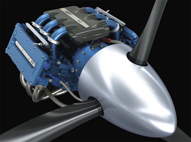
 Adept Ltd. used Inventor 3D solid modeling software from Autodesk to design its 320T, a 320-hp general aviation engine with a compact design that offers low vibration levels and high structural integrity. |
To help manufacturers toward that end, a myriad of software tools—many closely integrated with CAD tools—are being used to create digital prototypes of entire aircraft, to view and manipulate parts and assemblies of parts in digital design review sessions on the Web, and to simulate the reentry of NASA’s next-generation crew capsule into Earth’s atmosphere. And all this is taking place while manufacturers meet and exceed the strenuous flight-testing and certification processes required of them as they cut significant time and expense out of the overall design cycle.
 The Transition roadable aircraft being developed by Terrafugia Inc. is a light sport aircraft that can fold up its wings to become a road-legal vehicle. The aircraft’s beta prototype is currently being designed with plans for full production by the end of 2011. |
To find out how designers are doing that, we asked a handful of them what tools they considered indispensable. Their answers gave us an inside glimpse into the vital issues facing companies designing, building, and supporting aerospace products today.
Jump-Starting the Design Cycle
If the initial conceptual design of a product is not good, no downstream applications will save it, making the effective use of flexible 3D solid modeling tools crucial to getting proposed designs off to a solid start.
“The most important tools in our design process are clearly those used for the initial design and design validation,” says Richard Schulz, managing director at Adept Airmotive Ltd., a South African manufacturer of general aviation engines for the light aircraft market. “Without sound initial designs and the ability to operate accurately in the design stages, the use of other tools such as FEA would be compromised.”
Adept uses Autodesk Inventor 3D solid modeling software, Autodesk Vault data management software, as well as computational fluid dynamics (CFD), thermal analysis, air flow analysis, fluid flow and vibration analysis, static and dynamic finite element analysis (FEA) for validation and analysis of parts and assemblies, and product lifecycle management (PLM).
| Long Design Cycles, Longer Lifecycles
One thing has not changed despite the avalanche of sophisticated tools: it still takes a long time to design and build a new aircraft. For commercial aircraft, estimates range from five to ten years from the preliminary design though final design and certification testing. However, once the new designs take off, they are around for a long time. Civilian commercial aircraft are in service an average of 25-35 years. While there has been significant progress in both airframe and engine technology over the last decade, the implementation of such technology is limited by the number of opportunities for new projects. In some cases, combinations of improvements are introduced. For example, for one project a new airframe might use an existing engine (McDonnell Douglas DC-10/CF6-50), whereas in another a new engine might be applied to an existing airframe (Airbus 310/JT9D and Pratt & Whitney 4000). In other cases, design changes are made at the component level, the Boeing’s 757-300 using the RB211-535E4 LEC (low emissions combustor) engine and the Airbus 320 using the CFM 56-5B(DAC) (double annular combustor). The Boeing 777/GE90 represents an example of an all-new airframe/engine/combustor technology combination and was also the first commercial airplane to be designed in a completely paperless environment. — BS |
The company credits Inventor with helping it reduce the weight of the 320T (320 hp) engine by more than 130 lbs. over traditional piston engines of comparable horsepower. That makes the 320T 30 percent more fuel-efficient. Adept engineers produced accurate 3D models of the 320T before any parts were built, so they spent less time making changes and more time creating innovative designs, then simulating those designs under real-world conditions.
“Competitive advantage flows from the ability to drive down manufacturing, R&D, tooling, and prototyping costs,” says Schulz. “Good solid modeling tools reduce time-to-market, increase productivity, and reduce scrap and re-work costs. Solid models also facilitate clear inter-departmental and inter-operational communication, allow fluid migration of data to FEA, CAM, and PLM applications.”
Simulation Shaves Weight & Maintains Safety
Terrafugia Inc. is in the unique position of having no competition in the aerospace industry. Gregor Cadman, an engineer at Terrafugia, elaborates, “As a startup company creating a new type of product, our biggest challenge is not staying ahead of competitors, but to actually succeed in creating a viable product … and start delivering vehicles to customers.”
The Woburn, MA-based company has just 10 full-time employees working on a small light aircraft with foldable wings that doubles as a car. The Transition Roadable Aircraft’s design allows the aircraft to fold its wings and drive on any surface road. Once at the airport, the wings extend, and the aircraft is ready for takeoff. The company’s proof-of-concept vehicle has already completed its drive and flight testing, and the company plans to go into production by the end of 2011.
With such a small staff, the company’s engineers are responsible for all systems and structures from preliminary design down to materials selection. To help engineers adhere to its demanding design schedule, the company uses a slew of CAD-integrated tools. The design of the Transition aircraft was created using SolidWorks, FEA is handled by SolidWorks Corp.’s COSMOS software, and CFD analysis takes place with ANSYS Fluent.
“I would say that FEA tools are a great benefit in optimizing the weight of components and assemblies and for easily identifying critical areas and failure points … maintaining the proper safety margin,” says Cadman. “With our aerodynamic and weight requirements, CFD and FEA are playing a key role in tackling this challenge,” adds Cadman. “Without them, creating a light, robust, and safe vehicle which meets Light Sport aircraft requirements would be a potentially insurmountable challenge.”
It’s More than Rocket Science
As the manager of engineering tools and analysis at ATK Space Systems, Nathan Christensen knows a bit about computer-based tools. ATK, the maker of rockets for NASA and the U.S. military, uses them all: CAD/CAM/CAE, FEA, CFD, heat transfer codes, multiphysics, computational chemistry, ballistics, trajectory, and shock physics as well as customized internal codes.
As the primary contractor for the first stage of NASA’s new Ares I rocket as well as the vehicle’s Launch Abort System, ATK Space Systems knows how to deploy leading-edge computer tools to get the job done better, faster, and cheaper. And yet the tool that Christensen feels is most important to stay competitive in the aerospace market can be viewed as more of a business tool than an engineering tool.
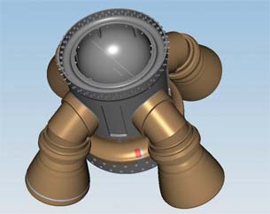 ATK used Siemens NX digita product development software to create the first stage of the Ares I Launch Vehicle for NASA as well as the vehicle’s Launch Abort System. This image shows the Launch Abort Manifold, located on the tower on top of the Ares rocket, which reverses and directs thrust into four nozzles on the Abort system. This very fast rocket motor exerts about a 10G force on the astronauts who refer to it as the “eyeballs out, eyeballs in” configuration. |
“Everyone has CAD tools now,” says Christensen, “They used to be somewhat of a distinguishing factor, but everyone has them now. We’ve got a supercomputer, Lockheed has a supercomputer, and Boeing has a supercomputer. That’s the price of admission,” says Christensen. “It’s really the management of data and the ability to efficiently manage your business that gives you an advantage over a competitor now.”
While the aerospace industry used to be considered a cost-plus business, this is no longer the case. And that’s why ATK has implemented Siemens’ Teamcenter PLM system.
“In aerospace today, nothing kills a program faster than an overrun,” says Christensen. “The government expects you to hit your targets, and they are not willing to fund the development indefinitely. They have become a lot more controlling with accounting systems.”
Christensen adds that it has become critically important for companies to improve on the bidding process, manage accounting, and keep costs in line. And, as collaboration continues to play an increasingly important role in large aerospace projects where many different companies are involved in the overall design, Teamcenter facilitates that collaboration. It enables the team to have a single source of data with which to collaborate with stakeholders.
PLM Provides One Point of Access
General Dynamics Robotic Systems (GDRS) is a world leader in tactical autonomous robotics and command and control systems. And it is also a firm believer in PLM. Despite having an arsenal of high-tech computer tools at its disposal, Laura Cook, Windchill administrator at GDRS, believes that PLM technology is what helps the company maintain a competitive advantage.
The company uses Pro/ENGINEER software to design its products and PTC’s Windchill to help maintain data security and facilitate collaboration within the company. Though it is currently being used for one specific project, the company plans to roll Windchill out across the enterprise over the next year and a half.
| HyperSizer Proves Use of Composites
In a series of critical, full-scale, physical tests recently completed by NASA, Collier Research Corporation’s HyperSizer composite analysis software accurately predicted the Composite Crew Module’s (CCM) successful performance under simulated flight. The CCM is the all-composite flight crew module Orion—part of NASA’s Constellation program to return man to the Moon or send him to Mars. HyperSizer was used throughout the almost three-year project to optimize the design, weight, and manufacturability of the CCM, which is constructed of honeycomb sandwich and solid-laminate composites. HyperSizer was the first NASA software to be licensed and commercialized as part of the agency’s effort to transfer technology to U.S. business and industry. “The CCM … represented an opportunity for the NASA family to get up the curve on experience with composites,” said CCM Project Manager Mike Kirsch. “Our analytical models predicted the response very well and now we’re much better informed.” HyperSizer is a structural sizing and design optimization tool that works in a feedback loop with FEA to automatically search for solutions that minimize weight and maximize manufacturability, and is particularly applicable to complex composite materials, and large structures. “I’ve been working with composites for 25 years and the CCM is the most complicated structure I’ve ever dealt with,” said Jim Jeans, chief architect for NASA on the project. Load testing of the CCM involved blanketing the vehicle with 280 linear strain gauges and 80 acoustic sensors that listened for fiber breaks in the layups. The structure successfully withstood tests of loads applied to the structure to simulate launch abort and parachute deployment, and an internal pressure test. — Lynn Manning |
“A good PLM system keeps your engineers from having to reinvent the wheel every time they need to do something,” says Cook. “It enables them to work together collaboratively without overwriting each other’s work. We’re storing all our data from start to finish in our PLM system so we’re not jumping back and forth from one system to another.”
All employees at GDRS access what they need in the Windchill system. Managers can pull numbers for budgets, engineers can find parts and models, checkers can access drawings, the shop floor can obtain manufacturing data, and personnel ordering parts can access parts lists—all within the Windchill system. “Everyone goes into that one data system and gets what they need surrounding the product,” says Cook. “Nothing is sent via e-mail to anyone inside the company; they just get a link back into the system.”
Remaining competitive means finding and using the right tools, and Cook believes that PLM technology plays a leading role in keeping GDRS competitive. “We do believe that PLM helps us maintain a competitive advantage, which is why going forward we’re rolling this out for the whole company. Without these tools, we would not be competitive at all.”